
VRF System Components: What's Actually Inside the System ?
Here’s a scene we run into a lot. Someone’s about to sign off on a VRF installation for their office or their villa, and they’ve got a rough idea of what VRF does — cools different rooms independently, saves on the electricity bill, all that. But ask them what’s actually inside the box, or why there’s copper piping snaking through the ceiling, and… blank stare. Understandable. Nobody hands you a wiring diagram before they ask for your money.
And honestly? You don’t need to become an HVAC engineer to make a smart decision here. But knowing the basic VRF system components — what each piece does, and why it matters — means you’ll actually understand what your contractor is quoting you for. Instead of just nodding along and hoping for the best.
So let’s open the hood.
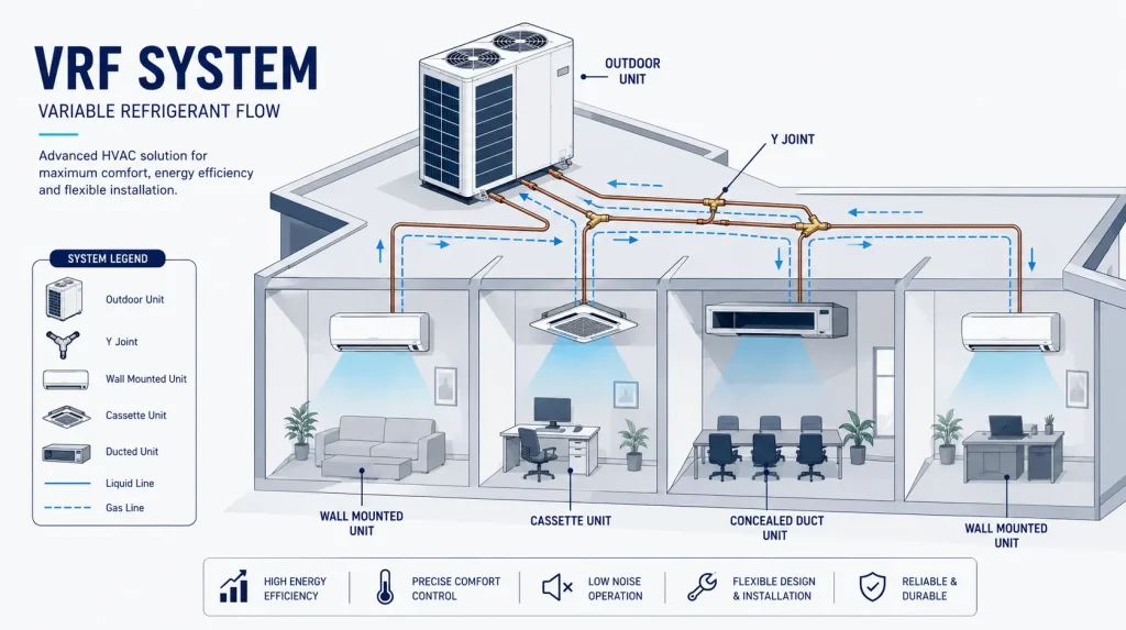
Quick Answer: What Are the Main VRF System Components?
Here’s the quick and short answer. A VRF setup is built from:
- One outdoor unit (sometimes more, on bigger jobs) — the heart of the system
- Multiple indoor units — one or more per room or zone
- Refrigerant piping — usually copper, connecting everything together
- Y joints or branch selectors — the traffic controllers that split refrigerant flow to each indoor unit
- A control system — thermostats, remotes, or a central controller managing it all
That’s the skeleton. Now let’s actually talk about why each piece matters, because “it’s a box that makes cold air” doesn’t really cut it once you’re spending real money.
How Does a VRF System Actually Work?
The VRF system working principle comes down to one idea: send exactly as much refrigerant as each room needs, no more, no less.
Think of it like a water pipeline feeding a neighborhood. A basic AC system is like one big tap that’s either fully open or fully shut — everyone downstream gets the same pressure whether they need it or not. A VRF system is more like a network of individual taps, each one adjusting on its own, based on how much water that particular house actually wants at that moment.
Mechanically, here’s the loop: refrigerant gets compressed in the outdoor unit (this raises its pressure and temperature), it travels through the piping to the indoor units, gives up or absorbs heat depending on whether you’re cooling or heating, and then heads back to the outdoor unit to start over. That’s the basic VRF refrigeration cycle — compression, condensation, expansion, evaporation, repeat. Nothing exotic about it. It’s the same core refrigeration cycle your fridge uses, just scaled up and split across a dozen rooms instead of one box.
The main difference is the inverter-driven compressor inside the outdoor unit. It doesn’t just switch on and off. It ramps up and down constantly, matching the real-time demand from every connected indoor unit. That’s the whole trick behind why VRF saves so much energy compared to older systems that only know “on” or “off.”
Types of VRF Systems
Not every VRF setup is built the same way, and the types of VRF system you choose depends on what the building actually needs.
1- Heat pump systems —
these run in one mode at a time, either cooling everything or heating everything. Simple, cost-effective, and honestly the right choice for most projects where the whole building has similar seasonal needs.
2- Heat recovery systems — these let different zones do different things at the same time. One side of the building cooling, another side heating. Sounds like magic, but it’s really just clever piping and control logic — the system moves heat from where it’s not wanted to where it is, instead of throwing it away.
Beyond that, VRF systems also get classified by piping arrangement — two-pipe setups for standard heat pump operation, and three-pipe setups when you’re running heat recovery. The number of pipes basically tells you how much flexibility the system has to move refrigerant (and heat) around independently.
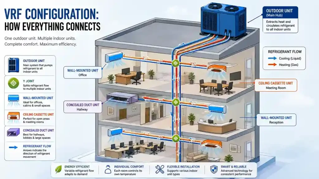
VRF Configuration: How Everything Connects
The VRF configuration is really just the layout — how many outdoor units, how many indoor units, and how they’re all wired together through the piping network.
A small office might run one outdoor unit feeding six or eight indoor units. A large commercial tower might need several outdoor units working together, feeding a hundred-plus indoor units across multiple floors. The beauty of it — and this is genuinely one of the best things about VRF — is that it’s modular. Need to add a zone two years down the line? In most cases, you can extend the system rather than ripping it out and starting over.
What a VRF System Diagram Actually Shows
If you’ve ever looked at a VRF system diagram or a VRF air conditioning system diagram and felt your eyes glaze over, don’t worry — it’s simpler than it looks once you know what you’re looking at.
Picture one box on the roof or outside the building (that’s your outdoor unit). From it, a set of copper pipes run out, hit a series of branch joints, and split off toward each room. At the end of each branch sits an indoor unit — mounted on the wall, tucked into the ceiling, whatever fits the space. Control wiring runs alongside the piping, connecting everything back to a central controller or individual remotes. That’s genuinely most of it. The complexity is in the sizing and the engineering, not in the concept.
1- The VRF Outdoor Unit: The Engine Room
The VRF outdoor unit, sometimes just called the VRF system outdoor unit, is where the real work happens. This is where the compressor lives, along with the condenser coil and the fan that rejects heat outside.
Think of it as the engine of a car. Everything downstream depends on it running smoothly. A well-sized outdoor unit, matched correctly to the total load of all the connected indoor units, is probably the single biggest factor in whether your system performs the way it’s supposed to for the next 15 years. Undersize it, and you’ll be fighting comfort complaints from day one. Oversize it wastefully, and you’re paying for capacity you’ll never use.
2- VRF Indoor Units: Where You Actually Feel It
The VRF indoor units are the part everyone actually interacts with — they’re what’s blowing cold or warm air into your room. Wall-mounted, ceiling cassette, concealed ducted, floor-standing — the outdoor unit doesn’t care which style you pick, as long as the total capacity adds up correctly.
This is honestly where a lot of the “personality” of the system shows up. A meeting room might get a discreet ceiling cassette. A server room might need a wall-mounted unit positioned for direct airflow. Every indoor unit runs its own thermostat logic, which is exactly what gives you that independent, zone-by-zone comfort VRF is known for.
3- VRF Copper Piping: The Circulatory System
If the outdoor unit is the heart, VRF copper piping is the circulatory system. Copper gets used specifically because it handles the pressure and temperature swings of refrigerant without degrading, and it’s a solid heat conductor — which actually matters here, since some heat transfer happens right through the pipe walls themselves.
This is also, honestly, where installations go right or wrong. Piping runs have to be sized correctly for the refrigerant volume they’re carrying, sloped properly for oil return, and brazed cleanly under nitrogen to avoid oxidation inside the pipe. Sounds like a small detail. It’s not.A poorly brazed joint today is a refrigerant leak eighteen months from now — and refrigerant leaks are quietly one of the most common reasons a VRF system underperforms.
4- The VRF Y Joint: The Traffic Controller
Now here’s a component most people have never heard of until they’re deep into a project: the VRF Y joint.
A Y joint VRF fitting — sometimes called a branch joint or a refrigerant branch selector, depending on the manufacturer — is exactly what it sounds like. It’s the point where one refrigerant line splits into two (or more), sending the right amount of refrigerant down each branch toward the indoor units downstream.
Why does this matter? Because get the joint placement or sizing wrong, and you can end up with refrigerant distribution problems — some rooms cooling beautifully, others barely keeping up, even though the outdoor unit is working fine. It’s a small fitting doing a genuinely important job, which is a pretty good summary of VRF systems in general — a lot of the performance comes down to details most people never see.
Why Any of This Matters to You ?
You’re probably not going to braze a joint or size a compressor yourself. That’s fair, that’s what a contractor is for. But knowing what a VRF heat pump system actually is, understanding that the outdoor unit and the piping and the Y joints all have to work together as one properly engineered system rather than a pile of parts that changes the conversation you have with whoever’s quoting your project.
At Maqsood & Sons, we’ve walked plenty of clients through exactly this, pulling up a rough diagram, pointing at each piece, explaining why the piping route matters as much as the brand name on the outdoor unit. It’s not complicated once someone actually walks you through it. It’s just rarely explained well.
Thinking Through a VRF Setup for Your Building?
If you're at the stage where you're comparing quotes and trying to figure out whether the system you're being offered is actually engineered properly — outdoor unit sizing, piping layout, joint placement, the whole thing — that's exactly the conversation Maqsood & Sons is happy to have with you.
Reach out, and we'll walk you through your building's layout and what a properly designed VRF system would actually look like for it — no guesswork, no generic parts list.
Book Your Service NowFrequently Asked Questions
An outdoor unit, one or more indoor units, refrigerant piping (usually copper), branch joints or Y joints to split the refrigerant flow, and a control system tying it all together.
It circulates refrigerant between an outdoor unit and multiple indoor units, adjusting the flow to match the real-time cooling or heating demand of each connected zone — rather than running everything at full blast or shutting off completely.
A heat pump system runs in one mode at a time , cooling or heating across all zones. A heat recovery system can do both simultaneously, moving heat from zones that don't need it to zones that do
It splits the refrigerant line into multiple branches, directing the correct amount of refrigerant to each indoor unit downstream. Poor Y joint placement or sizing is a common cause of uneven cooling across zones.
Copper handles the pressure and temperature changes of refrigerant reliably, conducts heat well, and holds up over the long piping runs a VRF system typically needs.